Hi Barry
Thanks for that. Yes, I would think adjustable but as you say everything I am reading suggests not to tinker with it.
My inclination at the moment is to try the spare pressure plate and disc, just to see how that changes things. In the meantime I've started drawing up a diagram with all the measurements I've taken just to see how far away it all is. I should be able to sketch the thing which will help me get my head around the problem. I'll do that first before I get my hands dirty again.
I wonder why there was no inspection port in the housing like the scout car? That would help!
Restoration of Ford M8 armoured car U.S Ordnance number 7373
-
Big D
- G-Captain

- Posts: 789
- Joined: Sat Sep 19, 2009 11:22 pm
- Location:
Re: Restoration of Ford M8 armoured car U.S Ordnance number 7373
Darryl Lennane
NZ
1943 Willys MB
1941 LP2A MG Carrier
1943 White M3A1 AOP
1942 Willys MBT
1944 Ford M8 Armoured Car
1945 Ford M20 Armoured Car
NZ
1943 Willys MB
1941 LP2A MG Carrier
1943 White M3A1 AOP
1942 Willys MBT
1944 Ford M8 Armoured Car
1945 Ford M20 Armoured Car
-
Big D
- G-Captain
- Posts: 789
- Joined: Sat Sep 19, 2009 11:22 pm
- Location:
Re: Restoration of Ford M8 armoured car U.S Ordnance number 7373
Hi Serge
I missed your reply before my last post. Are you saying I should be using the disc with the wafer type inner section rather than the one with the solid inner section? That is, the dark one in my photo, not the red one?
I missed your reply before my last post. Are you saying I should be using the disc with the wafer type inner section rather than the one with the solid inner section? That is, the dark one in my photo, not the red one?
Darryl Lennane
NZ
1943 Willys MB
1941 LP2A MG Carrier
1943 White M3A1 AOP
1942 Willys MBT
1944 Ford M8 Armoured Car
1945 Ford M20 Armoured Car
NZ
1943 Willys MB
1941 LP2A MG Carrier
1943 White M3A1 AOP
1942 Willys MBT
1944 Ford M8 Armoured Car
1945 Ford M20 Armoured Car
-
Big D
- G-Captain
- Posts: 789
- Joined: Sat Sep 19, 2009 11:22 pm
- Location:
Re: Restoration of Ford M8 armoured car U.S Ordnance number 7373
Hi all,
The Covid lockdown has slowed things down for me on the M8 but some progress has been made since we moved to Level 2 lockdown.
I fixed the joints around the water pump elbow and thermostat housing where coolant was seeping out. So far, so good, so hopefully that will cure my leaking problems. I refitted the lower engine panels around the engine. I couldn’t find an easy way to fit the panel on the exhaust side without removing the length of exhaust header which is bolted to the manifold. Has anyone else found this? I would have thought the panel would have been made so that it could be removed without disturbing the exhaust header pipe. The fitted panels certainly make the area around the engine bay look nice and neat.
I am not satisfied with the Hydrovac vacuum setup that I have so I will tidy that up a bit more over the next week. I have fitted the repaired voltmeter back into the instrument panel and that is working well.
I resolved my clutch issues by replacing the pressure plate. I’m not really sure how this did it, as the plates looked identical. However, I was did confirm that my original measurements were out by some 12mm so my original diagnosis of the problem wasn’t as bad as I had thought. I fitted the new pressure plate and gradually tightened it, while periodically sliding the transmission into and out of place and ensuring that there was still contact between the release bearing and the pressure plate fingers right through until I had fully tightened the pressure plate. I can only guess that the other pressure plate needed some adjustment. I am happy that it is resolved now though.
Once I was sure I had the clutch physically working I bled the clutch hydraulics using the pressure bleeder. This pressure bleeder does work well. What do you guys do for the bleed screw on the clutch slave cylinder? I have the original military type with the small ¼” ‘dust cap’ screw in the top of the bleed screw. I’ve found that during bleeding using the original bleeder, with the tapered thread, the fluid tends to come up the threads and spill out around the base of the bleeder before it works its way up the centre of the bleeder (with the dust cap off) and into the hose going into a jar.
I actually replaced the bleeder with a modern bleed screw with a bleeder nipple built into the top. It was the same thread (7/16-20) but what I didn’t realise is that the original bleeder has a tapered thread and the new one with the straight thread doesn’t seal properly.
How were these cylinders originally bled? Was it done the same way? Was it just a matter of them being loosened during the bleeding and allowing fluid to come out over the side of the cylinder? Is there a bleeder available with a tapered thread and a proper bleed nipple on the top?
The clutch now does work hydraulically and there is some satisfaction in seeing the slave cylinder operate while pushing the pedal! Thanks to Jonathan for his video of the clutch arm in operation as this showed the correct movement of the arm, and confirmed that I had everything set up correctly. The next time I am in the workshop I will run the engine with the drive-shafts disconnected and see if the clutch allows me to work my way through the gears in the gearbox which will tell me I have the clutch adjusted right. It looks good so far though.
I adjusted all the brakes and they have a good feel to them. However, I now have a problem with the wheel cylinders. The wheel cylinders were all stainless steel sleeved and I used NOS cups on the pistons which looked and felt good before I fitted them. After bleeding though, I noticed that four of the wheels were leaking hydraulic fluid though. I took two wheels off and the fluid appeared to have worked its way past both top and bottom cups on both wheel cylinders on both wheels, creating a small pool of hydraulic fluid at the bottom of the drum. One wheel was considerably worse than the other. I removed both cylinders on both wheels, pulled them apart and couldn’t see anything wrong with the cups or the bores.
My initial thought was that the original cups weren’t as effective with the modern brake fluid (Dot 4) and that perhaps the brake fluid back then had a higher viscosity. My other thought was that it was possible that the sleeves were made slightly too big for the original cups, but this was all done by my brake guy so it seemed unlikely. In the end, I took a wheel cylinder and pistons to a seal manufacturer and they made me a small number of new cups, enough to do two wheels.
When I got them back I found the new cups to be a very tight fit on the pistons and they looked to have a bit more material contacting the bore. I fitted these and bled the brakes, confident that it would solve my leaking problems. However, within a day of bleeding the brakes, the cylinders appear to be leaking again. I now wonder if the guy who fitted the sleeves didn’t seal the sleeve inside the cylinder properly and that the hydraulic fluid is working its way out between the sleeve and the cylinder. I plan to remove the drums again, remove the wheel cylinder caps and get a buddy to press the brake pedal gently to see if I can see where the fluid is coming out. I’m not sure how easy that will be to see but otherwise I figure the best bet is to return a couple of these cylinders to my brake guy so that he can bench test them.
Apart from the wheel cylinder problems, it is a good feeling knowing that all the hydraulics do actually work; throttle, clutch and brakes.
That is all for this week….
- Attachments
-
-
-
-
-
-
-
-
-
-
Darryl Lennane
NZ
1943 Willys MB
1941 LP2A MG Carrier
1943 White M3A1 AOP
1942 Willys MBT
1944 Ford M8 Armoured Car
1945 Ford M20 Armoured Car
NZ
1943 Willys MB
1941 LP2A MG Carrier
1943 White M3A1 AOP
1942 Willys MBT
1944 Ford M8 Armoured Car
1945 Ford M20 Armoured Car
-
sawbuck
- G-Command Sergeant Major

- Posts: 239
- Joined: Sun Sep 22, 2013 10:32 am
- Location: Vermont, USA
Re: Restoration of Ford M8 armoured car U.S Ordnance number 7373
I've never encountered tapered threads on a bleeder screw but in a similar situation with straight threads I have wrapped the screw once or twice around with plumbers tape (maybe called Teflon tape) to prevent leakage, or letting air in, when the screw is backed off the seat.
-
SURPDLR

- G-First Lieutenant

- Posts: 609
- Joined: Sun Oct 03, 2004 6:14 am
- Location: PENNSYLVANIA
- Contact:
Re: Restoration of Ford M8 armoured car U.S Ordnance number 7373
Darryl ,
As a public service announcement and info for all here is something I have had to deal with on a mates M20 Hydrovac install (and yes, that is a modern Type 3 that I also installed since the originals are near impossible to have rebuilt AND have them last!-
Petrol fumes are heavier than air. For reasons unknown the vacuum check valve is located BELOW the intake manifold. This means fumes WILL migrate down hill and attack the rubber material in the check valve. This problem is even more apparent if you have a float failure and flood the intake with raw fuel.
The end result of the above problem is petrol fumes and even raw fuel migrating into the hydrovac. This WILL destroy the rubber in the hydrovac. This led to 2 different hydrovac failures in my mates M20!!!!! And replacement of the check valve 2X.
My solution was inspired by the location of the check valve on a Half track. I fabbed a bracket that attaches to the Air Cleaner bracket in one of the existing holes that was there, and I think I also added a second hole. Other than that there no major changes to the M20. Made up new hard lines (1/2" tubing) and a new rubber supply line with stainless coil spring inside so it would not collapse.
Now the fumes can not "fall" into the check valve and hydrovac. As I type this it dawns on me this is even MORE of a problem with the stupid E10 ethanol additive fuel that is so common, since that stuff kill rubber VERY quickly!!
JEFF HAIN-MATSON
FRONT LINE MILITARY VEHICLES
WRIGHTSVILLE PA
717-252-4489
INDIAN 741
INDIAN 841
MATCHLESS G3
MATCHLESS G3L
AND SEVERAL OTHER WHEELED AND TRACKED TOYS!!
MVPA #1833
IMPS #1726
MVT #9362
FRONT LINE MILITARY VEHICLES
WRIGHTSVILLE PA
717-252-4489
INDIAN 741
INDIAN 841
MATCHLESS G3
MATCHLESS G3L
AND SEVERAL OTHER WHEELED AND TRACKED TOYS!!
MVPA #1833
IMPS #1726
MVT #9362
-
SURPDLR
- G-First Lieutenant
- Posts: 609
- Joined: Sun Oct 03, 2004 6:14 am
- Location: PENNSYLVANIA
- Contact:
Re: Restoration of Ford M8 armoured car U.S Ordnance number 7373
Darryl,
Wheel cylinders..... UGH!!!! Been there dealt with that.
My mates M20 had all 12 cylinders rebuilt at a VERY reputable brake re builder over here, they were sleeved when he had them done (Brass from memory). When we sent them we asked that they change to modern horizontal pistons and cup seals. They did not.
We had cylinders weeping before we were even done bleeding the brakes!!!!!
They went back and got the "Wagner kit upgrade we had asked for originally, they work FINE now and do not leak!"
The "O Ring" style piston was designed for vertical mounted cylinders because they thought it would reduce the amount of air to bleed out and that with a spring inside pushing the 2 cups outward there is a LOT more area to trap air (Horizontal style wheel cylinder).
My experience has been that a combination of pressure bleeder and pumping the pedal during bleeding gets the air out! You may go through a lot of fluid, but you will win in the end.
The other help is the manifold I showed you way back when that goes on the passenger side of the engine compartment to bleed the lines BEFORE they dip down into the engine compartment.
On the subject of brake fluid, there is conjecture that anything with Silicone is bad in a hydrovac vehicle since if/when it gets past the Hydrovac and gets burned in the engine it MIGHT turn gritty (silicate?) and cause internal engine damage.... I am not sure, but a JXD is NOT the place I want to test that theory either.... But I do swear by Silicone brake fluid in ALL the non Hydrovac vehicles I deal with! Not sure what they use to make DOT4....
I also have been told by an old time brake re-builder that Brake system rubber (old style rubber any way) is designed around DOT 3 swelling the rubber ever so slightly.... Not sure if DOT4 will do that. I know DOT5 does not seem to and sometimes you need to fill with DOT3 for a week or so, swell the rubber and flush DOT 5 into the system if that is what you want to end up with.
It is a shame to NOT use DOT5 since DOT5 does NOT eat paint, and would be a good fit in our Cars!!!
Just my 2 cents worth and experience of using DOT 5 for 30ish years. I have never used DOT4 so have no experience with it.
Good luck!!!
JEFF HAIN-MATSON
FRONT LINE MILITARY VEHICLES
WRIGHTSVILLE PA
717-252-4489
INDIAN 741
INDIAN 841
MATCHLESS G3
MATCHLESS G3L
AND SEVERAL OTHER WHEELED AND TRACKED TOYS!!
MVPA #1833
IMPS #1726
MVT #9362
FRONT LINE MILITARY VEHICLES
WRIGHTSVILLE PA
717-252-4489
INDIAN 741
INDIAN 841
MATCHLESS G3
MATCHLESS G3L
AND SEVERAL OTHER WHEELED AND TRACKED TOYS!!
MVPA #1833
IMPS #1726
MVT #9362
-
Big D
- G-Captain
- Posts: 789
- Joined: Sat Sep 19, 2009 11:22 pm
- Location:
Re: Restoration of Ford M8 armoured car U.S Ordnance number 7373
Hi Sawbuck
Thanks for that. That would be worth trying when I have to bleed the clutch again.
Hi Jeff,
Thanks for the two informative posts. That seems like a great idea with the hydrovac and I hadn’t considered that. I was not happy with the way I had set mine up and was concerned that I might have had oil coming back through to the hydrovac. As you say, the fuel would be a problem in there. I will look at a similar setup to what you did.
I was also interested in what you were saying about the wheel cylinders. I did some more experimenting with my brakes today. I took the wheel off one of the drums to have a look at what was going on.This wheel seemed to be leaking worse than others but it was one where I fitted the newly manufactured cups onto the pistons on both wheel cylinders. When I got the drum off I removed the wheel cylinder caps. I could see the left cylinder lower cap had fluid in it. The top cap on the cylinder and both caps on the other cylinder had moisture in there from the fluid but not a pool of fluid like the lower cap on the other side.
My plan was to pump up the line pressure with the power bleeder and watch what happened at the wheel cylinders. I didn't actually get to that point though and instead after wiping down the fluid from the wheel cylinders, I just watched where the fluid was coming out.
I think I might have to eat my words about the sleeves and the cylinders as on the left wheel cylinder the fluid is working its way between the piston and cups and the sleeve. It doesn't seem to be a problem with the sleeve at all on that side, and again I am back to the cups.
I will experiment a bit more tomorrow with some pressure from the bleeder but maybe it isn't the sleeves after all that is giving me grief.
Jeff - what is the Wagner kit upgrade you talk about? Maybe I need to look at that....
Darryl Lennane
NZ
1943 Willys MB
1941 LP2A MG Carrier
1943 White M3A1 AOP
1942 Willys MBT
1944 Ford M8 Armoured Car
1945 Ford M20 Armoured Car
NZ
1943 Willys MB
1941 LP2A MG Carrier
1943 White M3A1 AOP
1942 Willys MBT
1944 Ford M8 Armoured Car
1945 Ford M20 Armoured Car
-
SURPDLR
- G-First Lieutenant
- Posts: 609
- Joined: Sun Oct 03, 2004 6:14 am
- Location: PENNSYLVANIA
- Contact:
Re: Restoration of Ford M8 armoured car U.S Ordnance number 7373
Darryl,
Check the bottom of the cross over list in this thread for the WC kit numbers:
viewtopic.php?f=82&t=193010
Check the bottom of the cross over list in this thread for the WC kit numbers:
viewtopic.php?f=82&t=193010
JEFF HAIN-MATSON
FRONT LINE MILITARY VEHICLES
WRIGHTSVILLE PA
717-252-4489
INDIAN 741
INDIAN 841
MATCHLESS G3
MATCHLESS G3L
AND SEVERAL OTHER WHEELED AND TRACKED TOYS!!
MVPA #1833
IMPS #1726
MVT #9362
FRONT LINE MILITARY VEHICLES
WRIGHTSVILLE PA
717-252-4489
INDIAN 741
INDIAN 841
MATCHLESS G3
MATCHLESS G3L
AND SEVERAL OTHER WHEELED AND TRACKED TOYS!!
MVPA #1833
IMPS #1726
MVT #9362
-
Big D
- G-Captain
- Posts: 789
- Joined: Sat Sep 19, 2009 11:22 pm
- Location:
Re: Restoration of Ford M8 armoured car U.S Ordnance number 7373
Thanks Jeff
I will do some hunting around. An initial check shows no stock at a number of resellers but I will cast the net a bit wider.
I will do some hunting around. An initial check shows no stock at a number of resellers but I will cast the net a bit wider.
Darryl Lennane
NZ
1943 Willys MB
1941 LP2A MG Carrier
1943 White M3A1 AOP
1942 Willys MBT
1944 Ford M8 Armoured Car
1945 Ford M20 Armoured Car
NZ
1943 Willys MB
1941 LP2A MG Carrier
1943 White M3A1 AOP
1942 Willys MBT
1944 Ford M8 Armoured Car
1945 Ford M20 Armoured Car
-
SURPDLR
- G-First Lieutenant
- Posts: 609
- Joined: Sun Oct 03, 2004 6:14 am
- Location: PENNSYLVANIA
- Contact:
Re: Restoration of Ford M8 armoured car U.S Ordnance number 7373
Darryl,
You might have luck sourcing the pistons separately.
You might have luck sourcing the pistons separately.
JEFF HAIN-MATSON
FRONT LINE MILITARY VEHICLES
WRIGHTSVILLE PA
717-252-4489
INDIAN 741
INDIAN 841
MATCHLESS G3
MATCHLESS G3L
AND SEVERAL OTHER WHEELED AND TRACKED TOYS!!
MVPA #1833
IMPS #1726
MVT #9362
FRONT LINE MILITARY VEHICLES
WRIGHTSVILLE PA
717-252-4489
INDIAN 741
INDIAN 841
MATCHLESS G3
MATCHLESS G3L
AND SEVERAL OTHER WHEELED AND TRACKED TOYS!!
MVPA #1833
IMPS #1726
MVT #9362
-
Big D
- G-Captain
- Posts: 789
- Joined: Sat Sep 19, 2009 11:22 pm
- Location:
Re: Restoration of Ford M8 armoured car U.S Ordnance number 7373
Hi all,
I’ve been tied up with a few other projects so have only just been able to get back to working on the M8 again.
The problem brake wheel cylinders are on the agenda again. As you might recall I picked one of the wheels which was particularly leaky and removed the wheel and drum assembly and took the brake shoes off. I got a magnifying glass out and lay there for a bit and just watched the base of the wheel cylinder to see where the fluid was coming from. Just with line pressure I could see fluid seeping out between the piston and the sleeve.
I figured then that it was time for a change so I ordered two of the Raybestos type MK37 kits from Ross Prince in Australia. Again, I was sure these would cure my wheel cylinder woes and I fitted them to two of the wheels. I cranked up the pressure bleeder to 5 pounds and had started to bleed the system but got distracted by a few other things. When I came back half an hour later I noticed fluid pooling around one of the wheels. Dammit! I pulled the wheel and drum off that wheel and sure enough, fluid is obviously working its way out again. Fluid is also coming out on the other wheel I worked on, so clearly these new kits have not fixed the problem.
I am back to pointing the finger at the wheel cylinders and I figure there are only two possible causes. Either the brake guy did not seal the sleeves in the cylinders or the sleeves are slightly too big in diameter. I’m not sure that it can be anything else….Anyway, I have packaged up two of the wheel cylinders along with each of the cylinder kits I have tried; standard pistons with NOS donut cups; standard pistons with new manufactured donut caps; the Raybestos MK-37 kit with new pistons etc. These are all on their way back to the brake guy now who will try them on his bench and see if he can identify where the fluid is coming out.
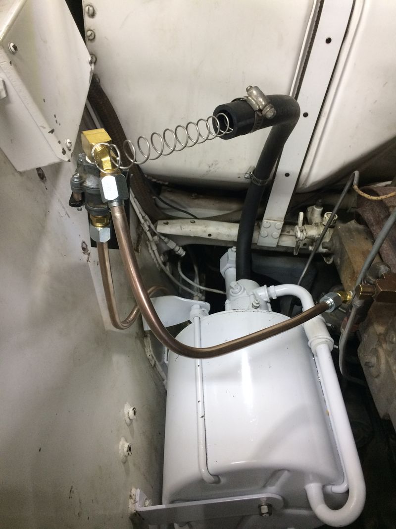
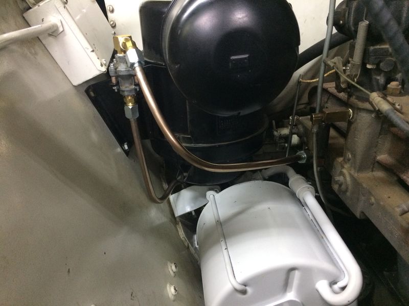
I liked Jeff’s idea about the hydrovac setup so much that I fabricated something like that myself. Like Jeff, I made up a small bracket that bolts to the side of the air-cleaner bracket. I also used a spare check valve from a White Scout Car that I had and ran that between the manifold and the hydrovac with some 3/8” solid tube. I will finalise this once I get the brakes sorted, but the picture should give you the idea.
I still have a small problem with the thermostat housing seeping a bit of coolant where it meets with the cylinder head. It is not much – maybe ¼ - ½ teaspoon - but just enough to be annoying. I find the design a bit frustrating that one of the studs is inside the housing and you can’t easily tighten both nuts on the sides of the thermostat housing down without disassembling the housing.
I picked up a nice Plum marked axe and have tidied this up and painted it to go with the shovel and pick that I have also freshened up.
Thanks to Charles, I now have the plate I was missing off the long electrical box in the engine mounting cross member in the engine bay. That finishes that part off nicely.
The .30cal spare parts box I got from Charles now has a coat of paint on it and I’ll add some decals to it shortly.
I got some exhaust tubing folded up and fitted that to the exhaust system. I don’t think I quite got the angle of the tubing perfect as it came out from under the hull but it looks pretty good.
I am still working on getting the ammeter going. I have three here which don’t seem to work so if anyone has a spare shunt type 100A ammeter I’d be interested.
That’s all for this week….
I’ve been tied up with a few other projects so have only just been able to get back to working on the M8 again.
The problem brake wheel cylinders are on the agenda again. As you might recall I picked one of the wheels which was particularly leaky and removed the wheel and drum assembly and took the brake shoes off. I got a magnifying glass out and lay there for a bit and just watched the base of the wheel cylinder to see where the fluid was coming from. Just with line pressure I could see fluid seeping out between the piston and the sleeve.
I figured then that it was time for a change so I ordered two of the Raybestos type MK37 kits from Ross Prince in Australia. Again, I was sure these would cure my wheel cylinder woes and I fitted them to two of the wheels. I cranked up the pressure bleeder to 5 pounds and had started to bleed the system but got distracted by a few other things. When I came back half an hour later I noticed fluid pooling around one of the wheels. Dammit! I pulled the wheel and drum off that wheel and sure enough, fluid is obviously working its way out again. Fluid is also coming out on the other wheel I worked on, so clearly these new kits have not fixed the problem.
I am back to pointing the finger at the wheel cylinders and I figure there are only two possible causes. Either the brake guy did not seal the sleeves in the cylinders or the sleeves are slightly too big in diameter. I’m not sure that it can be anything else….Anyway, I have packaged up two of the wheel cylinders along with each of the cylinder kits I have tried; standard pistons with NOS donut cups; standard pistons with new manufactured donut caps; the Raybestos MK-37 kit with new pistons etc. These are all on their way back to the brake guy now who will try them on his bench and see if he can identify where the fluid is coming out.
I liked Jeff’s idea about the hydrovac setup so much that I fabricated something like that myself. Like Jeff, I made up a small bracket that bolts to the side of the air-cleaner bracket. I also used a spare check valve from a White Scout Car that I had and ran that between the manifold and the hydrovac with some 3/8” solid tube. I will finalise this once I get the brakes sorted, but the picture should give you the idea.
I still have a small problem with the thermostat housing seeping a bit of coolant where it meets with the cylinder head. It is not much – maybe ¼ - ½ teaspoon - but just enough to be annoying. I find the design a bit frustrating that one of the studs is inside the housing and you can’t easily tighten both nuts on the sides of the thermostat housing down without disassembling the housing.
I picked up a nice Plum marked axe and have tidied this up and painted it to go with the shovel and pick that I have also freshened up.
Thanks to Charles, I now have the plate I was missing off the long electrical box in the engine mounting cross member in the engine bay. That finishes that part off nicely.
The .30cal spare parts box I got from Charles now has a coat of paint on it and I’ll add some decals to it shortly.
I got some exhaust tubing folded up and fitted that to the exhaust system. I don’t think I quite got the angle of the tubing perfect as it came out from under the hull but it looks pretty good.
I am still working on getting the ammeter going. I have three here which don’t seem to work so if anyone has a spare shunt type 100A ammeter I’d be interested.
That’s all for this week….
- Attachments
-
-
-
-
-
-
-
-
-
-
Darryl Lennane
NZ
1943 Willys MB
1941 LP2A MG Carrier
1943 White M3A1 AOP
1942 Willys MBT
1944 Ford M8 Armoured Car
1945 Ford M20 Armoured Car
NZ
1943 Willys MB
1941 LP2A MG Carrier
1943 White M3A1 AOP
1942 Willys MBT
1944 Ford M8 Armoured Car
1945 Ford M20 Armoured Car
-
Big D
- G-Captain
- Posts: 789
- Joined: Sat Sep 19, 2009 11:22 pm
- Location:
Re: Restoration of Ford M8 armoured car U.S Ordnance number 7373
Hi all,
Amongst other projects this week, I’ve done a bit more tinkering with different things on the M8.
I started up the engine again a week or so ago. It hasn’t run for nearly two months but started up almost immediately. I think the fuel pump on it is working very well. It was the first time I had the engine running since I fitted the exhaust system on it and sitting in the driver seat, I wasn’t sure it was running initially as the engine was very quiet. Here is another video: https://youtu.be/b6F-Bt4FQ_4
I had left the drive shafts off so I did some testing with the clutch and the gearbox. The clutch is definitely working well and while initially I was able to move through some of the gears, I found I was getting some binding and changing back from reverse into neutral was very tight.
I isolated the problem to the remote linkages, not the transmission. I had fabricated the longer of the two shafts that run between the transmission and the transmission control housing. Although I had the length of the long rod correct, the mounting hole spacing for the universal joint was out by a few mm. After drilling some new holes I put it all back together again and the transmission now shifts smoothly. I used some fairly sturdy pipe for this rather than solid rod. It seems sturdy enough so will see how that goes.
I ran the engine again and shifted through all the gears. It does shift very smoothly but the hydraulic clutch will take some getting used to. It just has a completely different feel to what I’m used to. Reverse gear does sound rumbly but I guess that is the cut of the gears?
Since that testing, I’ve fitted all the driveshafts ready for my road test. I was missing the little cap/cover that locks the universal joint bearing caps in place. After a bit of searching, I found some at a local scrap dealers. Interestingly, these are the same size as the covers that go in the hull above the sponsons for access to the tubing and wiring that runs through the channels on the sides of the vehicle. I have a couple of spares if anyone needs these.
I picked up a couple of M8 wheels a while back so I had the old run flat tyres removed and the wheels blasted and painted. I will swap these out with the two Scout Car/Half track wheels I currently have on the M8.
I spoke to my brake guy today. He has been working on the wheel cylinders I sent him. In his testing, he couldn’t fault one of the cylinders (!!) but does believe that the other one is leaking between the sleeve and the cylinder. He is going to press this sleeve out and fit a new one. Hopefully that will fix that one. He agreed with you guys in the US that the kits with the full cup and new pistons (the GMC type kits) are the way to go, so my plan going forward is to fit these new kits to each cylinder, bleed the system and monitor each wheel cylinder. If the cylinder develops a leak, I’ll send it back to the brake guy so he can redo the sleeve. It’s a lot of work, but I can’t see another way to progress things and it should all be for the best with the new pistons. That’s the plan, anyway….
A couple of other jobs I’ve been working on are a bridge weight sign and the turret ring indexing. Anthony from Axeholme Signs came to the party again and supplied me with a paint mask for the bridge weight sign and decals for the turret ring markings. The turret ring markings take some time to do but they do give a very nice result. Having the covers out of the vehicle is the way to do it. I'd say it would be a bit awkward doing it with them fitted around the turret.
That is all for this week…
- Attachments
-
-
-
-
-
-
-
-
-
-
Darryl Lennane
NZ
1943 Willys MB
1941 LP2A MG Carrier
1943 White M3A1 AOP
1942 Willys MBT
1944 Ford M8 Armoured Car
1945 Ford M20 Armoured Car
NZ
1943 Willys MB
1941 LP2A MG Carrier
1943 White M3A1 AOP
1942 Willys MBT
1944 Ford M8 Armoured Car
1945 Ford M20 Armoured Car
-
Aurel01
- G-Private First Class

- Posts: 10
- Joined: Thu Jul 09, 2020 1:30 pm
- Location:
Re: Restoration of Ford M8 armoured car U.S Ordnance number 7373
Wouaaaa good job 

-
armoured_smiler
- G-Sergeant First Class

- Posts: 94
- Joined: Fri Aug 07, 2009 4:00 am
- Location: UK
-
Big D
- G-Captain
- Posts: 789
- Joined: Sat Sep 19, 2009 11:22 pm
- Location:
Re: Restoration of Ford M8 armoured car U.S Ordnance number 7373
Hi Paul,
You could well be right there. I seem to recall the starter motor brush springs had a part number starting with MAY.
I still haven't got around to removing those wheel studs from the scout car front hubs for that diameter measurement you wanted. I'll try to do that over the next few days.
You could well be right there. I seem to recall the starter motor brush springs had a part number starting with MAY.
I still haven't got around to removing those wheel studs from the scout car front hubs for that diameter measurement you wanted. I'll try to do that over the next few days.
Darryl Lennane
NZ
1943 Willys MB
1941 LP2A MG Carrier
1943 White M3A1 AOP
1942 Willys MBT
1944 Ford M8 Armoured Car
1945 Ford M20 Armoured Car
NZ
1943 Willys MB
1941 LP2A MG Carrier
1943 White M3A1 AOP
1942 Willys MBT
1944 Ford M8 Armoured Car
1945 Ford M20 Armoured Car
Who is online
Users browsing this forum: No registered users and 34 guests