
Get the TM's! I used them extensively for the wiring diagrams in the back of 9-2320-280-20-3 and 387-24-2. Learn those wiring diagrams! I can wire a HMMWV in my sleep after doing this... Also use the 24P's to get NSN's for everything I list below. The stuff not in the 24P (ex the civvy TPS and various harness connectors) I will include the part numbers for and/or where I found it.
I would estimate I have 100 hours just into doing the swap (though I did change the engine with it). I spent many more reconditioning all the parts (rebuilt the engine, resealed the transfer case halves, put new seals in the tranny and t-case, etc.).
Before I started I made several major decisions on how I would proceed.
1. What kind of TCM: Aftermarket or Military
The aftermarket TCMs generally do not require an engine speed signal, which simplifies things a bit. They also come with their own harness pre-made. However, the cases are not sealed from the elements (which is a major con for me) and they can cost over $1,000.
The military TCM is dirt cheap used (comparatively) and is in a sealed enclosure. However you have to buy an incredibly expensive harness which is a bear to install, or make your own (not as hard as you'd think). Most importantly, it requires an engine speed signal for the torque converter lock up to work.
I chose to go with the military TCM for several reasons. For all of the pro reasons listed above, and also because for roughly the same price as an aftermarket TCM, I could swap in 6.5NA engine with a bung for the speed sensor sensor
2. How to supply the engine speed signal: Oil Pump Drive Sensor or Crank Sensor
1994 H1's with a 6.5NA used an oil pump drive with a speed sensor meant to feed the TCM. The speed sensors on the 6.2 HMMWV's for the STE/ICE have the wrong number of pulses per rev and can't be used. However if you want to keep the 6.2 you can get a hold of one of the H1 parts. I think there are two kinds out there, one of which can be directly connected to the TCM and one which needs some kind of signal processor board by a company called Dakota Digital between it and the TCM. I'll leave that up to you to figure out.
Since I chose to replace my engine with one that has a bung for the crank sensor, I used that. It's also correct for the truck. Alternatively you can replace the front of your 6.2. If you do make sure to get the piece that goes on the crank with the four tits to trip the sensor.
3. How to supply 12v to the TCM: DC-DC power supply or dual voltage alternator
I have been using a DC-DC converter to step down to 12v to power cellphone chargers and stuff for a while now and it works well. It's mounted up on the radio tray though and I don't rely on it for essential functions since it is not sealed. I can't really recommend this, with how easy a dual voltage alternator swap is.
I put in a dual voltage alternator with the new engine. How I did that is shown here: viewtopic.php?f=63&t=221530
Anyway, on to the necessary parts based on my decisions above. I haven't included hardware in the list. Some I was able to re-use, most I just replaced.
Parts List
----------------------------------------------
Transmission Parts
-----------------------
4L80-E Transmission
4L80-E Crossmember
Transmission Mount (Old one can be re-used, but don't) - Hummerpartsguy
Transmission Shift Linkage
Dipstick Tube - Hummerpartsguy
Dipstick Tube Seal - Hummerpartsguy
Dipstick - Hummerpartsguy
4-Speed Shifter
Transfer Case Parts
-----------------------
NP-242 Transfer Case
Transmission to Transfer Case Adapter
Transfer Case Adapter Drain Plug - Hummerpartsguy
Transfer Case Shift Linkage
Drive line
-----------------------
A2 Front Drive Shaft (Only the section between the slip joint and the T-Case) (Alternatively, lengthen the existing shaft by 2? inches)
A2 Rear Drive Shaft (Shortened 7/8" if you plan to keep the drive shaft parking brake)
Electrical
-----------------------
Transmission Computer
Transmission Warning Lamp - Kascar
Transfer Case Lock Lamp - Hummerpartsguy
Double Brake Switch
Double Brake Switch Linkage - Hummerpartsguy
Engine Speed Sensor
Throttle Position Sensor - AIRTEX / WELLS Part # 5S5080 (TPS146) or BWD EC3003
Fan Cutout Switch Bracket - Kascar
Fan Cutout Switch Linkage
TCM 12v Power Relay - Hummerpartsguy
TCM 12v Power Circuit Breaker
If you plan to build a harness:
16ga Prestolite Wire - Erik's Military Surplus
Harness Stub with TCM Connector - Get this cut out of a scrapped truck
Transmission Connector - ebay
Transmission Speed Sensor Connector (x2) - ebay
Rubber Bullet Connectors (Male and Female) - Erik's Military Surplus
Rubber Y Connectors (Female) - Erik's Military Surplus
Headlight Bulkhead Connectors (Male) - Erik's Military Surplus
2-Pin Sureseal Connectors (Receptacle) - http://www.newark.com" onclick="window.open(this.href);return false; P/N 120-1804-000
Sureseal Connector Crimp Pins - http://www.newark.com" onclick="window.open(this.href);return false; P/N's 030-2196-001 and 031-1267-001
16ga Ring Termals for Battery Connections
Otherwise buy an A2 body harness, and maybe a matching engine harness! $$$
Now to the task at hand...
Pulling the old drive train wasn't bad. I removed the radiator and pulled the whole stack out the front. Having access to a gantry was amazing! And buy the red thing. It was worth it's weight in gold.

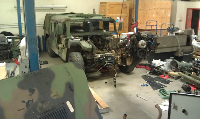
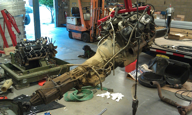

Installation of the tranny and transfer case is straight forward. It all goes in the same way the old stuff came out. I installed the engine and tranny together, then bolted up the transfer case afterward. I found it easier to do it that way because the old transfer case got hung up a bit on the driver side transmission crossmember mount bracket on the frame at the same time as the engine was having a hard time clearing the driver side motor mount. Dodging one at a time is easy, dodging both at the same time was harder. Rather not juggle that on the way back in too.
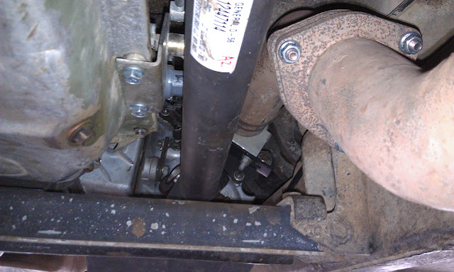
Here's some pics of the finished installation:
Clearances were just fine on the muffler and the fuel tank. There's plenty of room in there, even with the drive shafts installed.
Now for the differences.
The first obvious problem is the dipstick tube. Apparently the old one can be bent to fit, but I didn't want to have to heat it and have it get kinked and messed up, so I bought the right one and a new dipstick to match.
The next problem is the transmission and transfer case cooling hard lines. If you have 1995/1996 4L80 then the fittings are the same and they will work if you bend them around enough until they fit. Basically they are too long because the fittings on the TH400 come out the side at about 45 degrees angled forward and they come straight out the side of the 4L80 at 90 degrees. So you have to be creative in taking up some of that length by making some convoluted bends. Or you could cut them and re-barb the ends.
If you have a 1997 or later 4L80 you are sh it out of luck. The fittings are different and my understanding is you have to order a length of tube with a fitting pre-attached. I don't know the part number but I remember reading about it in the HKB.
There is a bypass valve that I haven't gotten a hold of yet that get's T'd into the cooler lines. Basically if the temperature of the tranny fluid is not high enough, it skips the cooler and returns back to the tranny and t-case. This is so that in cold climates the tranny can warm up enough. The TCM doesn't like it if the tranny temp sensor reads too low and does funny stuff or throws a code or something. Not too much of a worry for me since I live in a warm climate, but I'll install it later when I find one.
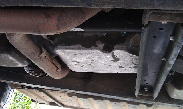
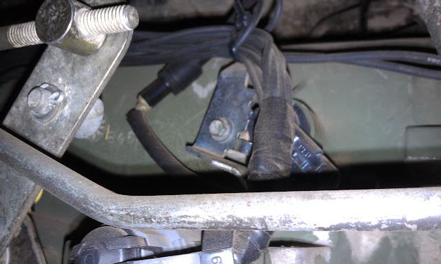
Then is the exhaust. There was a small heat shield in the way of the muffler clamp that mounts to the top of the transfer case, now that that transfer case is a couple of inches farther rearward. I had to drop the muffler and cut the shield off. Luckily it is only welded at four tabs and cuts off quick. Grind down the welds so you don't cut yourself later!
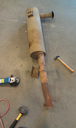
In this picture you can see the two rings around the exhaust where the clamp used to be.
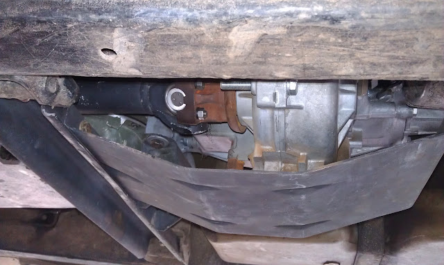
Now you have to figure out your drive shaft situation.
I was able to get the A2 section of front drive shaft that I needed so I didn't have to lengthen mine. I just installed new u-joints and called it a day. You only need the very first shaft that connects to the transfer case. The part on the other end of the slip joint with the pillow bearing can be re-used. If you do lengthen your shaft, be aware you will have to change the yoke on the transfer case or get an adapter u-joint because the 242 and A2 shaft use a larger size u-joint than the 218 and A0.
On the rear the only piece you can use is the flange for the parking brake rotor, since the slip joint moves into the transfer case itself and you can't have two slip joints. I am keeping my drive shaft parking brake because it works well on my truck and I want to have all four service brake calipers be cheap and interchangeable. I had the drive shaft shortened by a local shop and they did a nice job. The u-joint to install the parking brake flange onto the A2 shaft is the same size on both sides and is a very common one.


Next, the shifter and new indicator lights. The shifter just drops in, but you have to drill holes for the indicators. T-case lock lamp goes outboard. The for-aft spacing of these is kind of touchy because there is some geometry under the body you need to avoid.
There is an all new linkage for the transmission. Also make sure your tranny has the two lever crap on it. It picks up two bolts on the bottom of the oil pan.

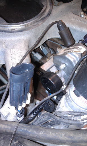
Now we work on the injection pump. The fan cutout switch and cam need to come off. The switch gets relocated the left head with an L-shaped bracket to hold it and a new linkage that you can try to make out of the old modulator cable if you can't find the real one. You also have to make extensions for the wiring harness to reach the new location.
The civvy throttle position sensor gets mounted where the cutout switch was. Install it loose for now because you will have to adjust it later. Make sure to reinstall the roll pin that held the cam on before you mount the TPS because that is what actuates it. You can not use a military TPS without making a modification to the IP. The shaft is too large.
If you are going to replace the oil pump drive with one with a new sensor, now is a good time. Otherwise install the crank sensor in the bung if it isn't already. If your engine is set up as a 6.2 replacement, you will probably have a freeze plug in the bung. Knock it in unless you know of a good way (slide hammer?) to pull it out. The bore is LONG, like several inches. You can knock it in without worrying about it getting hung up. It'll just drop to the bottom of the pan... not that I recommend leaving it there, but it won't hurt anything.
The brake pedal switch also has to go. The new version has an added switch to tell the TCM to unlock the torque converter when you step on the brakes. The positioning is a little different, so the linkage to the brake pedal needs to be replaced with a wider one.

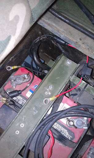
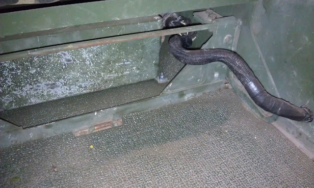
The relay went on the back wall of the battery box. It's the gray rectangle just barely visible inboard of the battery. 24v ignition switched power actuates it and it switches 12v power to the tranny and TCM so you don't have to turn your tranny on and off when you start or stop the truck...
I couldn't get a circuit breaker for a reasonable price so I just bought a mini inline fuze holder from NAPA. It's a 15A breaker, so I used the same size fuze. When I do get one, I'll mount it just above the relay and drill a hole for the reset button to go out the back.
I don't plan on installing A2 seats so I mounted the TCM under the driver's seat and drilled a hole in the body to pass the wire harness through. Since I'm starting at the TCM connector and terminating the far ends in place, the hole doesn't have to be large enough to fit that massive connector, just the cable bundle. Make sure you locate the hole far enough back so that adjusting the seat doesn't chop it.
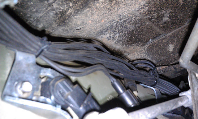
Now onto the wiring! Here's my harness. It's all built off of a TCM connector stub that had about a foot of wires on it. I loosely ran the wires to estimate the length I needed to each location, then soldered them all onto the stub and tagged them.
Based on the harness stub I got and some first hand accounts of cut up harnesses, it appears that everything is discreet wire without shielding with a mesh braid pulled over it to bundle it. The wires listed as twisted pair on the schematic are not in fact twisted together. Some of the wires are regular 16ga black harness wire and some of the wires (sensor signals generally) are 18ga white wire. Where the black wire insulation is rubbery and soft and slightly tacky, the white wire insulation is hard plastic-y and slippery. I've seen it before in other military applications, its just another standard wire type.
I used the 16ga Prestolite wire throughout because it was readily available.

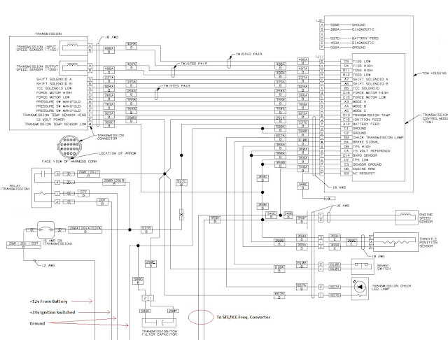
This is the wiring diagram out of the TM.
The two wires I had trouble with during harness soldering were the 12v power to the TCM and the A/C request. I mis-took the lowercase "j" for 12v on the face of the TCM connector for a lower case "i", but when capital "J" (the only J on the connector) had no continuity I left it until the end when I only had one wire left and the process of elimination resolved it for me. The A/C request line I left floating. It shows on the schematic as "not used", but there is still a stub of wire drawn. The wire was also present in my harness stub. I was concerned that maybe it was tied to ground or something but after driving around for a couple of days with no problems, it appears I did it right.
I did not install the filter capacitor or the STE/ICE frequency converter or wiring.
I have read that with the A/C request asserted, the line pressure is bumped up a couple of PSI because typically the engine is run at a slightly higher idle when the A/C compressor is engaged.
For routing I followed the factory harness wherever possible, zip-tying my wires to to it.
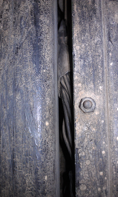
I started by passing the whole bundle through the hole I drilled behind the front seat. This ends up in the channel between the body and the frame rail where the factory body harness runs, so I followed that up to the front of the truck. The only tight spot is where the bundle runs up the side of the frame rail to get above it. The factory cutout in the body is too small for a bundle this large, so I had to spread the wires out and wrap them in some insulation so they won't rub through on the frame rail.
Once above the frame rail, in front of the parking brake lever, I arrived at the main junction point. This is where everything branches off.
For switched 12v power distribution (which goes to five or six different places) I made terminal blocks out of Y-connectors and headlight bulkhead connectors. Take two Y-connectors and join them with a bulkhead connector. Now you can connect four wires together. Add a one more Y-connector with another bulkhead connector and you can connect a fifth wire. This way I wouldn't have to figure out how to get a good heat shrink seal over 5 wires soldered together... It's not possible! The way I did it is bulky, but in the end quite robust. Also a couple of the sensor signals share a common ground, so I did the same thing with them.
The bulk of the bundle from the TCM, including TISS and TOSS goes up by the STE/ICE connector, and back to the transmission.
One wire goes up and forward along the driver side to the engine speed sensor (the second ESS wire is described below).
One wire goes up and into the cabin by the speedometer cable to the brake pedal switch.
Two wires go up the driver side and over the engine to the passenger side to the TPS (the third TPS wire is described below).
Two wires go in the body channel across the top of the transmission over to the battery box for battery constant 12v and ground.
One wire goes up to the trans warning lamp.
One wire (sensor ground) terminates here at one of the "Y-connector terminal blocks". Out of the terminal block a wire goes forward for the engine speed sensor ground, a wire goes up to the transmission connector for the temperature sensor ground and a wire goes up to the TPS for the TPS ground.
One more wire (switched 12v) terminates here at another "Y-connector terminal block". Out of the terminal block a wire goes over the top of the tranny to the relay in the battery box, a wire goes up to the brake pedal switch, a wire goes up the to the transmission connector, and a wire goes up to the trans warning lamp.


The brake pedal switch, and engine speed sensor use 2-pin Sureseal connectors. I got crimp pins since I have access to a crimper, but I think they also make solder pins.
The switch pinout doesn't matter, but the ESS does.
ESS pinout:
White: Signal
Black: Ground
The TISS and TOSS use standard automotive weatherpack connectors, but there is a short (6"?), 2-wire harness that has a weatherpack on one end and a 2-pin Sureseal on the other, so I terminated my harness with Sureseal connectors for them too. Pay attention because the two sensors are terminated with opposite polarities.
The TPS is also supposed to use a short harness bit with a 3-pin Sureseal connector on one end and a weatherpack connector on the other. I cut the weatherpack connector off of the civvy TPS and used three individual rubber bullet connectors instead. If you are using the military TPS you can't cut off the weatherpack because it is integrated in to the case of the sensor.
TPS Pinout:
Grey: +5v Reference
Blue: High
Black: Ground
For the main transmission connector you have to get a "harness repair connector" for a GM vehicle and solder it onto the harness.
Now to supply 24v ignition switched power to turn on the relay you have to go behind the instrument panel and put in another "Y-connector terminal block" off of the lower of the two circuit breakers on the side of the steering column. Run a wire from there to the relay in the battery box.
I ran a second wire from the terminal block down to transfer case lock indicator switch. Then ran a wire from the switch up to the lock indicator lamp. The lock indicator lamp has a ring terminal on one lead that terminates at one of the parking brake lever mounting bolts.
And that's it! All done!
After I built everything, before I applied power, I rang out all the pins in the whole harness with a meter to check my work.
It all fired up on the first try and I've been driving it around for about five days now. The fourth gear makes a world of difference, even on surface roads. It shifts into fourth between 40 and 45 and the truck is practically silent. Except for the whine of the transfer case and buzzing of body vibrations from all over
Augi


